


Installation and Maintenance Guide for Vortex Flowmeters
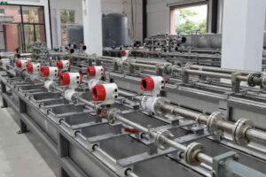
Vortex flowmeters, designed based on the Karman vortex street principle, are widely used in monitoring the flow of industrial fluids (gases, liquids, steam).
Correct installation and standardized maintenance play a crucial role in ensuring measurement accuracy and extending the service life. The following details the installation, daily maintenance, and repair guidelines for vortex flowmeters.
I. Installation Details of Vortex Flowmeters
1.1 Pre-installation Preparations
1.1.1 Instrument Inspection
- Specification Verification: Carefully confirm the specifications of the flowmeter, including diameter, pressure rating, medium temperature, and explosion-proof rating, ensuring an accurate match with the actual operating conditions.
- Appearance Check: Conduct a comprehensive inspection of the instrument’s appearance to ensure no damage. Also, inventory the accessories to confirm that flanges, bolts, gaskets, converters, etc., are complete.

1.1.2 Pipeline Condition Check
- Pipeline Cleaning: Ensure the inner wall of the pipeline is smooth and free of rust, welding slag, and other debris. Thoroughly purge the pipeline if necessary.
- Diameter Matching: The inner diameter of the pipeline must be exactly the same as the flowmeter diameter, eliminating any eccentricity or reduction in diameter.
1.2 Installation Location Selection
1.2.1 Straight Pipe Section Requirements
- General Situation: Upstream of the flowmeter, reserve at least 10D (D is the pipeline diameter) of straight pipe section; downstream, retain at least 5D of straight pipe section to ensure stable fluid flow.
- Influence of Disturbance Sources: If there are disturbance sources such as elbows, valves, or reducing/enlarging pipes upstream, extend the upstream straight pipe section to 20D, while maintaining 5D downstream.
1.2.2 Avoid Harsh Environments
- Vibration Sources: Keep away from vibration sources like compressors and pumps to prevent interference with the instrument.
- Heat Sources: Avoid proximity to high-temperature sources, such as steam pipelines, to prevent instrument damage.
- Electromagnetic Interference: Stay away from strong electromagnetic interference sources like frequency converters and transformers. The installation environment temperature should be controlled between -20°C and +60°C, with humidity ≤85% RH.
1.2.3 Installation Direction
- Horizontal Installation: The axis of the sensor should be parallel to the horizontal plane, and the fluid direction must strictly follow the arrow marking. Ensure the pipeline is full of medium to prevent gas accumulation or liquid vaporization.
- Vertical Installation: Suitable for liquid measurement, with the fluid flowing from bottom to top to ensure the pipeline is full of medium and avoid bubble retention.
- Inclined Installation: When used for steam or gas measurement, ensure the pipeline has a certain slope for easy drainage of condensed water. A steam trap should be installed in the steam pipeline.
1.3 Installation Steps
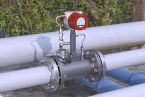
1.3.1 Flange Connection
- Coaxial Alignment: Precisely align the flowmeter flange with the pipeline flange coaxially.
- Bolt Tightening: Tighten the bolts evenly. The gasket should not protrude into the pipeline to avoid interfering with the flow field. Ensure there are no leaks at the connection.
1.3.2 Connection between Sensor and Converter
- Cable Selection: The signal cable between the sensor and the converter must be a shielded cable, laid through a metal conduit, and kept away from high-power lines to prevent electromagnetic interference.
- Wiring Specification: Ensure the correct polarity of the power supply during wiring, with a grounding resistance ≤10Ω. In explosion-proof environments, strictly follow the explosion-proof wiring specifications.
1.3.3 Flow Direction Marking
Carefully confirm that the arrow direction on the flowmeter housing is consistent with the actual fluid flow direction. Reverse installation is strictly prohibited, as it can easily lead to measurement errors or even damage to the instrument.
1.4 Precautions for Installing with Special Media
1.4.1 Liquid Measurement
- Avoiding Bubbles: To prevent bubbles in the pipeline, an exhaust valve can be installed upstream. When installing vertically, the fluid should flow from bottom to top.
1.4.2 Steam Measurement
- Pipeline Insulation: Insulate the pipeline.
- Condensate Pot Installation: Install a condensate pot upstream of the flowmeter to ensure the steam at the sensor is in a saturated state.
- Condensate Drainage: Regularly drain the condensate to prevent water hammer impacts.
1.4.3 Gas Measurement
Ensure the gas in the pipeline is a single-phase flow and avoid liquid mixing. A gas-liquid separator can be installed downstream.
II. Daily Maintenance and Repair Guidelines
2.1 Daily Inspection Items
2.1.1 Instrument Display Check
Check the converter’s display screen daily to confirm whether the flow data, cumulative volume, and alarm codes (if any) are normal. Pay attention to any zero drift or abnormal fluctuations, such as non-zero readings when there is no flow.
2.1.2 Appearance and Connection Check
Inspect the instrument housing and flange connections for leaks and looseness. Check the sensor surface for dirt, corrosion, or mechanical damage. Also, examine the sealing condition of the cable interface for aging and damage.
2.1.3 Environmental Condition Check
Monitor whether the temperature, humidity, and vibration of the installation environment are within the allowable range. Judge whether there is abnormal pipeline vibration by listening or touching the pipeline.
2.2 Regular Maintenance
2.2.1 Cleaning and Rust Removal
- Dirt Cleaning: Every 3 – 6 months, clean the dirt and rust on the sensor probe and the inner wall of the pipeline (liquids are prone to scaling, and steam is prone to carbon deposition). Use a soft brush or non-corrosive solvent for wiping, being careful not to damage the probe surface.
- Anti-corrosion Treatment: Apply anti-corrosion treatment to exposed metal parts, such as flanges and bolts. Rust-proof paint or grease can be applied to prevent rust.
2.2.2 Sealing Test
Conduct a pressure leakage test on the flange connections annually. Apply soapy water and observe for bubbles, especially in high-pressure conditions, to prevent medium leakage from affecting measurement and avoid safety accidents.
2.2.3 Signal Calibration
Calibrate the instrument every 1 – 2 years, which can be done through actual flow calibration or online zero calibration. Before calibration, ensure there is no fluid flow in the pipeline and set the converter to zero. For high-precision measurement scenarios, it is recommended to send the instrument to a professional metrology institution for verification.
2.2.4 Component Replacement
If aging gaskets, damaged cable insulation, abnormal converter display, etc., are found, replace the corresponding components in a timely manner. For explosion-proof instruments, power off first and strictly follow explosion-proof regulations when replacing components.
2.3 Common Fault Troubleshooting and Repair
2.3.1 No Flow Display or Weak Signal
- Possible Causes: Loose wiring or cable breakage; converter power failure; damaged sensor probe.
- Solutions: Check and re-tighten the wiring; replace the power supply or converter; return to the factory for repair or replace the probe.
2.3.2 Excessive Measurement Deviation
- Possible Causes: Insufficient straight pipe section, turbulent flow field; uncompensated changes in medium conditions (temperature, pressure); probe fouling or corrosion.
- Solutions: Increase the straight pipe section or install a flow conditioner; reset the temperature and pressure compensation parameters; clean or replace the probe.
2.3.3 Intense display data fluctuations
- Possible Causes: Bubbles or two-phase flow in the pipeline; excessive pipeline vibration; electromagnetic interference with the signal.
- Solutions: Install an exhaust valve or gas-liquid separator; increase pipeline supports to reduce vibration; strengthen cable shielding and grounding.
2.3.4 Abnormal Cumulative Volume Jumps
- Possible Causes: Solid particles in the fluid impacting the probe; incorrect converter parameter settings, such as range and filtering coefficient.
- Solutions: Install a filter upstream; recalibrate the parameters and extend the filtering time.
2.4 Maintenance Records and Logs
Establish detailed maintenance logs, recording the time, content, and results of each inspection, cleaning, and calibration, as well as the handling process of abnormal faults and information on replaced components. This facilitates tracing the equipment status and predicting the maintenance cycle.
III. Safety Precautions
3.1 During Installation and Maintenance
Cut off the process pipeline medium, relieve pressure, and power off. Confirm that there is no pressure or high temperature on-site before operation. In explosion-proof environments, use explosion-proof tools and strictly prohibit opening the cover while powered on.
3.2 Working at Heights
If the instrument is installed at a height, operators must wear safety ropes and be supervised by a dedicated person.
3.3 Medium Protection
When in contact with corrosive media, wear protective equipment to prevent direct skin contact or inhalation of volatile gases.
IV. Long-term Out-of-use Maintenance
If the instrument needs to be out of use for a long time (more than 3 months), take the following measures:
- Empty the Medium: Empty the medium in the pipeline, remove the sensor (or the entire unit), and store it in a dry environment free of corrosive gases.
- Power Off and Dustproof: Power off the converter and cover it with a dust cover to prevent dust accumulation.
- Pre-use Inspection: Before reusing, conduct a comprehensive inspection, calibration, and sealing test.
Through standardized installation and regular maintenance, the measurement accuracy and reliability of vortex flowmeters can be effectively improved, reducing the downtime failure rate.
In case of complex faults, such as probe damage or internal circuit failures, it is recommended to contact the manufacturer’s professional technicians. Do not disassemble the instrument by yourself to avoid affecting its performance.
SHARE:
More Posts for You

We are always ready to help
Got a question? Our support team
will go the extra mile so you can have an easy and enjoyable experience with Mejor.

Get More Benefits Since Submit The Info Form
*We respect your confidentiality and all information are protected.